Project: Build your own radar
Figure 1: Transmitter/Exciter module for generating and modulating the radio frequency.
Project: Build your own radar
Principle of Operation
Initially, a continuous radar (CW radar) is to be built which already has the capability of an FMCW radar. Since it emits power continuously rather than in pulses, the radar is safe for humans. The transmitters power will be in the milliwatt range, several decimal values far below the permissible limits. The design is such that extensions are also possible after successful testing of the CW and FMCW radar function. Thus, an extension to a pulsed radar will be possible later, using an intrapulse modulation (so-called “chirp radar”). An easy changeover between these two modes by a control signal is also possible.

Figure 2: Impression of a block diagram

Block diagram
In general, a transmitter is required which is variable in frequency by a control voltage. A small Raspberry Pi is designed to generate the control voltage for the modulation via a digital-to-analog converter.
The receiver is basically formed by a small cheap USB oscilloscope. Unfortunately these USB oscilloscopees are not sensitive enough, so an additional pre-amplifier must be installed. In my example given (ELV-Versand Article-Nr. 68-09 93 35) The upper cut-off frequency of this oscilloscope is 200 kHz - which is just as usable. However, it would be better to select a more expensive device that can handle several megahertz and whose software includes the Fast Fourier Transform (FFT).
Radarsignal processor should be this Raspberry Pi. Even if the generation of the tuning voltage consumes a lot of the computing power, it should actually also provide the operating system, ie here: evaluation and display of the echo signal. If it does not work for time reasons, then a second Raspberry Pi can be used.
Antenna
The antenna is the element where most of the money can be wasted. If only a single antenna is used (as shown in figure 2), then you need a ferrite circulator. This one costs in the Internet between 200 and 600 euros, plus high shipping costs. The qualitative difference is in the isolation between the transmission and the receiving path. The isolation has a value of usually between 16 and 23 dB. Two separate equal antennas can only be purchased for a fraction of this effort, or even be self-made. Since this is a Wi-Fi frequency band, two arbitrary Wi-Fi antennas can be used.
If the antenna is mounted in front of a parabolic reflector, then either two parabolic reflectors are required (as shown here) or else the version with a ferrite circulator must be used. Only one primary radiator can be positioned precisely in the focal point of a single parabolic reflector. If you want to use a single parabolic reflector with a horn feed, Then you'll need the version with the ferrite circulator obligatory. Both components (horn radiator and ferrite circulator) are comparatively expensive. But two horn feeds you can build yourself if necessary.
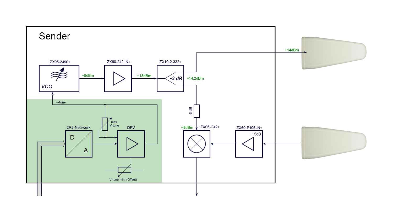
Figure 3: Block diagram of the transmitter in version without ferrite circulator but with two antennas

Figure 3: Block diagram of the transmitter in version without ferrite circulator but with two antennas
Transmitter
The most important component of the transmitter is a Voltage-Controlled Oscillator (VCO) which can sweep over the released frequency range. It should be better if its tuning voltage and operating voltage is in the range of 5 volts in order to limit the number of necessary main voltages. Such a component is the VCO ZX95-2490+, that is available at Mini-Circuits at a reasonable price of about 45 €. But be careful! This one VCO must not be connected to the operating voltage without load, otherwise it will immediately be irreparably damaged.
Figure 1 shows a test setup, which is, however, slightly modified from the block diagram shown in Figure 2. The amplifier for the RF here has a much to high gain. Therefore an attenuator of -9 dB is connected to the output of VFO (this one is an additional protection). The sum of all attenuations and gains shall have a level of approximately 7 dBm at the receivers down converter local-oscillator input jack. (Don't forget the damping of the plugs!)
In Figure 3, the components are highlighted in green, for which a separate printed circuit board must be designed. It is a simple passive digital to analog converter (DAC) with an R/2R network which uses the digital outputs (GPIO) of the Raspberry Pi in the simplest case. Because the DAC only works passively, its speed depends only on the Raspberry Pi. It requires no synchronization pulses. For a sawtooth pulse, the Raspberry Pi must only increment these outputs binary. A triangle pulse is also possible without problems. Whether 8 bits or 12 bits are used has an influence on whether the sawtooth pulse is rather a stepping voltage, or not. The available frequency range is swept by either 256 or 4096 substeps. At 250 MHz bandwidth, these steps are either 1 MHz or 62 kHz in size. If the sawtooth pulse is to be about 1 ms long, the Raspberry Pi must count with about 4 MHz.
The subsequent operational amplifier (OPV) makes a tuning voltage from the logic levels which fully utilizes the range of the VCO. Without this OPV, the VCO would also work but the saw tooth then has only a magnitude of less than one volt.
Of course, a simple analog sawtooth generator would fill this job. This has however the disadvantage that the radar can thereby really only this one sawtooth. The radar then cannot be extended to other modulation patterns.
Receiver
For the time being, the receiver consists practically only of a small USB oscilloscope. The model mentioned in the calculation is extremely simple and can process analog frequencies up to 200 kHz only. This cut-off frequency is actually too low, therefore this version is only provisional suitable for functional testing. It should be replaced later by a more powerful model.
With a fixed tuning voltage, the circuit as shown in Figure 2 operates as a CW radar. In this case only Doppler frequencies can be detected and no distances can be measured. The expected Doppler frequencies in this frequency range can be calculated and are, for example, approximately 320 Hz at 30 km/h.
If the selected USB oscilloscope module cannot calculate a display like a spectrum analyzer, it is now very difficult to detect an echo signal. The oscilloscope shows sinusoidal frequencies, which move completely non-synchronously across the screen. They are similar to ripple and can quickly be confused with it. If, however, during a movement of a metallic object in front of the antenna, this apparent ripple changes in amplitude and frequency, then the radar works.
Calculation
The following component list can already provide an overview of the required material used up to this point and a small incomplete cost approach:
| Assembly | Type | Quantity | Supplier | Price |
|---|---|---|---|---|
| Voltage Controlled Oscillator | ZX95-2490+ | 1 | Mini-Circuits | 42,89 € |
| Amplifier (Buffer) | ZX60-242LN+ | 1 | Mini-Circuits | 57,55 € |
| Power-Splitter | ZX10-2-332+ | 1 | Mini-Circuits | 33,46 € |
| Low Noise Amplifier | ZX60-P105LN+ | 1 | Mini-Circuits | 73,25 € |
| Mixer | ZX05-C42+ | 1 | Mini-Circuits | 39,40 € |
| Parabolic antenna | TL-ANT2424B | 1 | ca.40,00 € | |
| Ferrite circulator | AT11B-TE207-AF | 1 | Aaren | 155,00 € |
| USB-Oscilloskope | USB-MSM | 1 | ELV | 39,95 € |
| Raspberry Pi | Typ B+ | 1 | ELV | 32,95 € |
| Cable RG402, SMA-plugs... | 50,00 € | |||
| Total | 589,44 € |
(This calculation does not take into account the fact that a full-fledged computer is required for the function, because it is already present mostly.)
This calculation was made around 2018. Apart from the fact that prices rarely change downwards, so unfortunately some of the assemblies of Mini-Circuits are no longer produced.