Overview of Radar Transmitter
The radar transmitter produces the short duration high-power rf pulses of energy that are radiated into space by the antenna. The radar transmitter is required to have the following technical and operating characteristics:
- The transmitter must have the ability to generate the required mean RF power and the required peak power.
- The transmitter must have a suitable RF bandwidth.
- The transmitter must have a high RF stability to meet signal processing requirements
- The transmitter must be easily modulated to meet waveform design requirements.
- The transmitter must be efficient, reliable and easy to maintain and the life expectancy and cost of the output device must be acceptable.
The radar transmitter is designed around the selected output device and most of the transmitter chapter is devoted to describing output devices therefore:
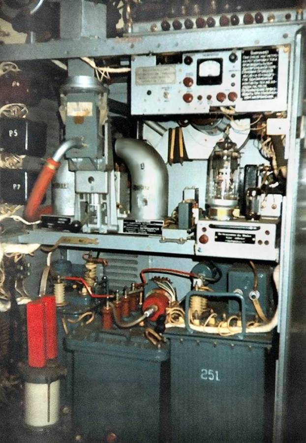
Figure: keyed-oscillator type transmitter of russian P-37 (“Bar Lock”)
- One main type of transmitters is the keyed-oscillator type. In this transmitter one stage
or tube, usually a
magnetron
produces the rf pulse. The oscillator tube is keyed by a high-power
dc pulse of energy generated by a separate unit called the
modulator.
This transmitting system is called POT
(Power Oscillator Transmitter). Radar units fitted with a POT are either
non-coherent or
pseudo-coherent.
- Power-Amplifier-Transmitters (PAT) is used in many recently developed radar
sets. In this system the transmitting pulse is caused with a small performance in a
waveform generator.
It is taken to the necessary power with an amplifier following
(Amplitron,
Klystron or
Solid-State-Amplifier).
Radar units fitted with an PAT are
fully coherent
in the majority of cases.
- A special case of the PAT is the
active antenna.
- Even every antenna element
- or every antenna-group
- A special case of the PAT is the
active antenna.
Pictured is a keyed oscillator transmitter of the historically Russian radar set
P-37 (NATO-Designator: „Bar Lock”).
The picture shows the typical transmitter system that uses a
magnetron
oscillator and a waveguide transmission line. The magnetron at the middle of the figure is connected to the
waveguide by a coaxial connector. High-power magnetrons, however, are usually coupled directly
to the waveguide. Beside the magnetron with its magnetes you can see the
modulator with its
thyratron.
The impulse-transformer and the
pulse-forming network with the charging diode and the high-voltage transformer are in
the lower bay of this rack.
Solid-state transmit/receive modules appear attractive for constructing phased array radar systems. However, microwave tube technology continues to offer substantial advantages in power output over solid-state technology. Transmitter technologies are summarized in the following table.
| Technology | Maximum Frequency | Peak/ Average Power | Typical Gain | Typical Bandwidth | |
|---|---|---|---|---|---|
| POT | Magnetron | 95 GHz | 1 MW / 500 W )¹ | - | Fixed…10% |
| Impatt diode | 140 GHz | 30 W / 10 W )¹ | - | Fixed…5% | |
| Extended interaction oscillator (EIO) | 220 GHz | 1 kW / 10 W )² | - | 0.2% (elec.) 4% (mech.) | |
| PAT | Helix traveling wave tube (TWT) | 95 GHz | 4 kW / 200 W )¹ | 40…60dB | Octave/ multioctave |
| Ring-loop TWT | 18 GHz | 8 kW / 400 W )¹ | 40…60dB | 5…15% | |
| Coupled-cavity TWT | 95 GHz | 100 kW / 25 kW )¹ | 40…60dB | 5…15% | |
| Extended interaction Klystron (EIK) | 280 GHz | 1 kW / 10 W )² | 40…50dB | 0.5…1% | |
| Klystron | 35 GHz | 50 kW / 5 kW )¹ | 30…60dB | 0.1…2% (inst.) 1…10% (mech.) | |
| Crossed-Field amplifier (CFA) | 18 GHz | 500 kW / 1 kW )¹ | 10…20dB | 5…15% | |
| solid-state Silicon BJT | 5 GHz | 300 W / 30 W )³ | 5…10dB | 10…25% | |
| GaAs FET | 30 GHz | 15 W / 5 W )¹ | 5…10 dB | 5…20% | |
Table 1: Pulse Radar Transmitter Technology
Source: Tracy V. Wallace, Georgia Tech Research Institute, Atlanta, Georgia.