Parabolic Antenna
(primary radiator)
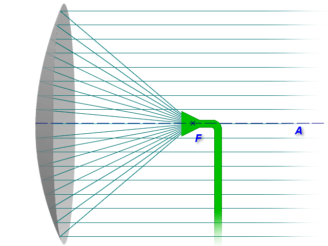
Figure 1: Principle of parabolic reflector antenna

(primary radiator)
Figure 1: Principle of parabolic reflector antenna
Parabolic Antenna
A parabolic reflector, dish, or mirror is a device that is used to collect or project energy such as electromagnetic waves. Alter incoming plane waves traveling along the same axis as the parabola into a wave that is spherical and they all meet at the focus of the reflector.
The parabolic dish antenna is the form most frequently used in the radar engineering of installed antenna types of. Figure 1 illustrates the parabolic antenna. A dish antenna consists of one circular parabolic reflector and a point source situated in the focal point of this reflector. This point source is called “primary feed” or “feed”.
The circular parabolic (paraboloid) reflector is constructed of metal, usually, a frame covered by metal mesh at the inner side. The width of the slots of the metal mesh has to be less than λ/10. This metal covering forms the reflector acting as a mirror for the radar energy.
According to the laws of optics and analytical geometry, for this type of reflector all reflected rays will be parallel to the axis of the paraboloid which gives us ideally one single reflected ray parallel to the main axis with no sidelobes. The field leaves this feed horn with a spherical wavefront. As each part of the wavefront reaches the reflecting surface, it is shifted 180 degrees in phase and sent outward at angles that cause all parts of the field to travel in parallel paths.
This is an idealized radar antenna and produces a pencil beam. If the reflector has an elliptical shape, then it will produce a fan beam. Surveillance radars use two different curvatures in the horizontal and vertical planes to achieve the required pencil beam in azimuth and the classical cosecant squared fan beam in elevation.
Figure 2: Parabolic radiation pattern
Figure 2: Parabolic radiation pattern

Figure 2: Parabolic radiation pattern
This ideal case shown in figure 1 doesn't happen in the practice. The real antenna pattern of parabolic antennas has a conical form because of irregularities in the production. This main lobe may vary in angular width from one or two degrees in some radars to 15 to 20 degrees in other radars.

Figure 3: Horizontal cross-section of a real measured radiation pattern of a parabolic antenna in logarithmic scale, determined in a field experiment
The radiation pattern of a parabolic antenna contains a major lobe, which is directed along the axis of propagation, and several small minor lobes. Very narrow beams are possible with this type of reflector.
The gain G of an antenna with parabolic reflector can be determined as follows:
.print.png)
.png)
(1)
- ΘAz = beamwidth in azimuth angle
- ΘEl = beamwidth in elevation angle
This is an approximate formula but gives a good indication for most purposes while noting that gain will be modified by the illumination function.
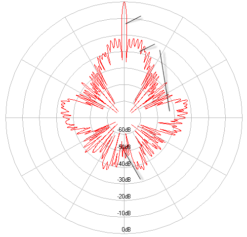
Figure 3: Horizontal cross-section of a real measured radiation pattern of a parabolic antenna in logarithmic scale, determined in a field experiment
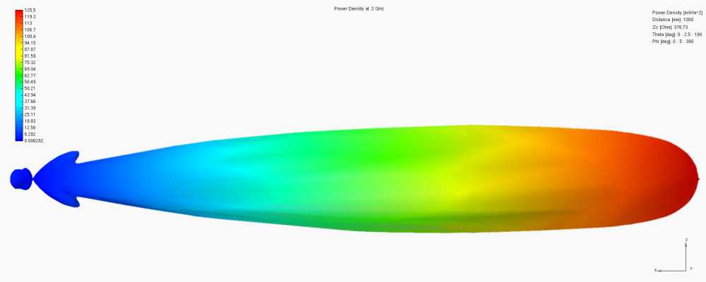
Figure 4: 3D radiation pattern of a parabolic antenna, determined using a simulation program

Figure 4: 3D radiation pattern of a parabolic antenna, determined using a simulation program
Note: The differences between Figure 2 and Figure 4 make sense: in Figure 2 the range is linear, so the size of the sidelobes is not recognizable. Figure 4 shows the range in a logarithmic scale, the sidelobes are so easily recognizable, but the peak of the main lobe is flattened.
“Single Curvature” or “Double Curvature” parabolic antenna

Figure 5: “Single Curvature” Reflektor and “Double Curvature” reflector in comparison
A “Single Curvature” or 2D-Reflector has instead of a focal point a focal line. Parabola is what you see when you look at the end of it. This parabola is duplicated on a straight line. Type 1022 is an example given for this kind of reflector.
At “Double Curvature” or 3D-Reflector the surface is generated by a parabola revolving around its axis. The parabola can be seen from every aspect angle.